Home
Projects
TenTec PTO's are infamous for their need to be rebuilt after a few
years because the grease on the drive screw starts to harden and must be cleaned
and re-lubricated. Probably the most difficult part of this rebuild
process is figuring out how to get the darn PTO out of the radio. Of the
four PTO's that I've rebuilt, the removal process was similar - but
different. So, as I was going through this process, I decided to document
the steps for myself, for the next time I had to do it. Then I thought it
would be a good idea to make this available to others so they don't have to go
through the discovery process as I did. So here's my documentation on the
removal of the PTO from an Argonaut 515. You can click on any of the
photos for a larger picture.
First, a few suggestions... Get something nice and soft to place
your Argonaut on. I used a double layer of bubble wrap, but a folded towel
is probably a better choice. You will be
handling it a lot, and we don't want to get any scratches or bruises as a result
of fixing up the PTO, do we. Next, get some containers for the screws,
washers, and brackets that will be removed. I used some empty film cans,
and labeled each can so I could get the right hardware back where it came
from. Tune the frequency dial all the way to the bottom of the band.
This will make it easier to remove and restring the dial cord later.
OK, here we go.
1) Remove the Top and Bottom Panels. The top panel is
easy: (2) screws along the back edge. The bottom panel is a little
trickier. Remove the (4) screws holding the speaker cover to the bottom
panel.
 Then remove the (6) screws holding the bottom panel to the
chassis. Remove the (2) screws holding either side panel to the back
panel, and gently tilt the side panel out so you can lift the bottom panel on
that same side up. Reposition the side panel back against the
chassis, and put the screws back in (you won't lose
them that way). The bottom panel can be lifted up now, but remember the
speaker is still attached, so don't go too far with the panel. There are
two slots on opposite sides of the speaker hole in the bottom panel.
You can slide the speaker away from the panel by tilting the speaker so it will
slip through those slots. To protect the speaker cone, I put a plastic
container cover over the speaker and held it in place with some masking tape.
Then I put the speaker into the radio and taped it so it wouldn't move
around. It probably would have been easier just to unsolder the two
speaker wires, and reattach them later. Next time I'll do it that way.
(It sure would have been a good idea for Ten-Tec to have included a
little board connector for that speaker so it could be removed easily.)
Then remove the (6) screws holding the bottom panel to the
chassis. Remove the (2) screws holding either side panel to the back
panel, and gently tilt the side panel out so you can lift the bottom panel on
that same side up. Reposition the side panel back against the
chassis, and put the screws back in (you won't lose
them that way). The bottom panel can be lifted up now, but remember the
speaker is still attached, so don't go too far with the panel. There are
two slots on opposite sides of the speaker hole in the bottom panel.
You can slide the speaker away from the panel by tilting the speaker so it will
slip through those slots. To protect the speaker cone, I put a plastic
container cover over the speaker and held it in place with some masking tape.
Then I put the speaker into the radio and taped it so it wouldn't move
around. It probably would have been easier just to unsolder the two
speaker wires, and reattach them later. Next time I'll do it that way.
(It sure would have been a good idea for Ten-Tec to have included a
little board connector for that speaker so it could be removed easily.)
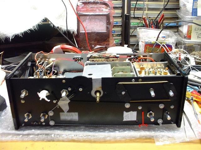
2) Remove the Front Panel. First, remove all the
knobs. Mine were fastened with small Allen set screws. The tuning
skirt is removed by grasping it on opposite sides with your fingers, and pulling
it off the PTO shaft. Be patient, and careful as you're doing this; you
don't want to lose the tuning skirt and throw it across the room. There
are (2) screws on the bottom edge of the Front Panel that have to be
removed. Then there are (2) screws inside the radio that sandwich the
Front Panel to the Side Panels. There is (1) screw in the
top corner of each Side Panel that must be loosened a turn or two (no need to
remove them). Now you should be able to lift off the front panel, but
again do it carefully because there's a small cable of (3) wires running from
the front panel to a connector on the front of the chassis. Pry the
connector off, and now the Front Panel will be free. Set the Front Panel
somewhere safe where it won't get scratched or bumped. And while the
panel is off, this is a good time to clean it. Everyone has their
favorite cleaner. Mine is Windex glass cleaner. I spray some on a
soft rag, and then wipe off the panel.
3) Remove the Two Screws on the Front Panel. These screws
are located on the black front panel on either side of the PTO tuning
shaft. This is the
simplest step, and I thought I was finished. But the PTO is still held in
place by (2) more screws.
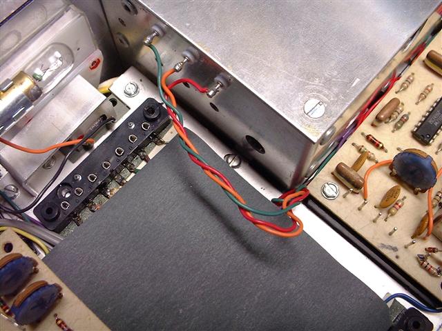
 4) Unsolder Wires from PTO. This is a good time to take a
break, and unsolder the five wires from the four PTO terminals. There are
three terminals side-by-side, and (1) on the back side of the PTO box. The
terminal on the back of the box has (2) white wires on it. Make a sketch
before you remove the wires so that you can get them back to their proper
terminals. Be sure to include the colors of the wires in your sketch.
4) Unsolder Wires from PTO. This is a good time to take a
break, and unsolder the five wires from the four PTO terminals. There are
three terminals side-by-side, and (1) on the back side of the PTO box. The
terminal on the back of the box has (2) white wires on it. Make a sketch
before you remove the wires so that you can get them back to their proper
terminals. Be sure to include the colors of the wires in your sketch.
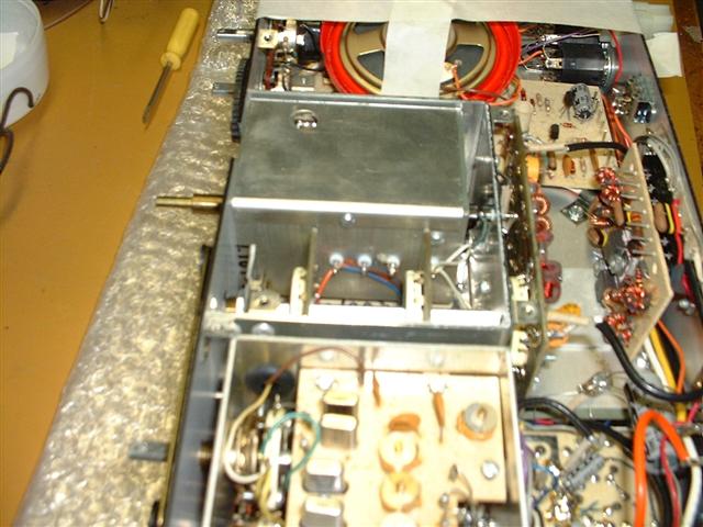
 5) Remove Bracket and Screw from Side of PTO. With the
front of the radio facing you, and the bottom of the radio facing up, you will
be looking at the PTO which is inside a larger aluminum shield. On the
left side of the PTO, on the outside of the shield, is a bracket which is used
to fasten the Bottom Cover to the chassis. Remove the screw that holds the
bracket to the shield. Set the bracket and screw in a container, and label
it "Step 5". This will help with reassembly. It's not
necessary to remove the other screw that's on the PTO, located close to the
bracket.
5) Remove Bracket and Screw from Side of PTO. With the
front of the radio facing you, and the bottom of the radio facing up, you will
be looking at the PTO which is inside a larger aluminum shield. On the
left side of the PTO, on the outside of the shield, is a bracket which is used
to fasten the Bottom Cover to the chassis. Remove the screw that holds the
bracket to the shield. Set the bracket and screw in a container, and label
it "Step 5". This will help with reassembly. It's not
necessary to remove the other screw that's on the PTO, located close to the
bracket.
6) Remove the IF Board. The IF Board is to the left of the
PTO as you look at the chassis, bottom up, and front forward. Remove the
(2) screws that hold down the board. Now remove the nut that holds the AF
Gain/Power switch to the front panel using a 1/2" socket or wrench.
Move this control slightly to the left so that you'll have room to remove the IF
Board completely from the radio, and set it in a safe place. The IF Board
has chassis connections at both ends of the board. Be extra careful in
lifting the board up so you don't damage the board. I used a pair of long
nose pliers to grab the board between the mounting holes and the ends of the
board, and wiggled VERY GENTLY until the board started to move. Then I put
the pliers down and did the rest by hand. Work at the ends of the
board; don't pull up in the center!
 7) Remove the SSB Board. The SSB Board is to the left of
the PTO as you look at the chassis, top up, and front forward. It also is
held by (2) screws, and has chassis connectors at both ends. Use the same
procedure as in Step 6 to remove this board.
7) Remove the SSB Board. The SSB Board is to the left of
the PTO as you look at the chassis, top up, and front forward. It also is
held by (2) screws, and has chassis connectors at both ends. Use the same
procedure as in Step 6 to remove this board.
8) Remove the Lower PTO Bracket Screw. With the SSB Board
removed, you will see a screw going through the chassis to a bracket that
attaches to the PTO on the bottom side of the chassis. Remove this screw
and set it off by itself for a moment.
9) Remove the Lower Bracket from PTO. Now turn the chassis over, and hiding under the insulating paper, you'll see the bracket mentioned in Step
8. Remove the screw and bracket from the PTO. Now the PTO should be
loose and almost ready to remove. Tape the bracket and its (2) screws that
go with it together and label them "Step 8 & 9".
 10) Remove Dial Cord from PTO Tuning Shaft. Before you can remove the PTO, you'll have to remove the dial cord from the PTO Tuning Shaft. If you tuned all the way to the low end of the scale before starting this endeavor, you're all set. Lift the dial cord off the Adjuster pulley and the two white pulleys next to the S-Meter. Then slide the cord off the pin on the PTO shaft, and unwrap the dial cord. To keep everything together, I "restrung" the dial cord, making a loop-back around the Adjuster pulley, and taped the cord to the front face to keep it in position until ready
for reassembly.
10) Remove Dial Cord from PTO Tuning Shaft. Before you can remove the PTO, you'll have to remove the dial cord from the PTO Tuning Shaft. If you tuned all the way to the low end of the scale before starting this endeavor, you're all set. Lift the dial cord off the Adjuster pulley and the two white pulleys next to the S-Meter. Then slide the cord off the pin on the PTO shaft, and unwrap the dial cord. To keep everything together, I "restrung" the dial cord, making a loop-back around the Adjuster pulley, and taped the cord to the front face to keep it in position until ready
for reassembly.
11) Remove the Sheet Metal Screw on the back of the VFO shield.
This is hard to do because you can't get a straight shot at the head of the
screw. You could remove that assembly on the back of the shield for better
access to the screw, but I was tired of removing boards, so I used a long-nose
pliers on the pointed end of the screw to loosen it, and then backed the screw
out with the pliers turning the screwhead a little bit at a time. I think
this is the hardest step to do, so just have patience.
12) Remove the PTO. Finally, you can reach in and lift out
the PTO. Before you dig into the PTO, carefully remove the pin on the
shaft of the PTO (where the dial cord ties to). You can put this in the
container with the other PTO hardware.
13) Clean and Re-grease the PTO. I've read that most
PTO's don't really need new parts, just a good cleaning and re-greasing.
After having rebuilt three PTO's, I would agree with that statement. So,
you probably don't need to buy the rebuild kit for $30. Just get some
mineral spirits for cleaning off the old grease, and some Mobil 1 Synthetic
Grease or some white lithium grease for re-greasing the PTO. I've used
both of these, and am satisfied with both. The white lithium grease is a little
thinner, and the PTO tuning is a little easier. But I would recommend
either one. Follow the directions that come with the Ten-Tec PTO Rebuild
Kit, or - if you're just cleaning and re-greasing, refer to N5FC's (now K5ESE)
article "Rebuilding the Century 21 PTO/Vernier". You can find
this at http://www.io.com/~n5fc/c21_pto.htm. As you can tell, it's for a Century 21, but the PTO's are the same inside, so
just follow the PTO Disassembly and Assembly directions.
14) Reassemble the Argonaut 515. Nothing tricky here, you've already done the hard part. Just work your way back through each step. This is where your
sketch of the wires, and the parts in the labeled film cans will come in very
handy. When I got to the dial cord reassembly, I found that a pair of
tweezers came in handy for tying a knot in the dial cord to put over the pin.
15)
Check the PTO Tuning. With the 515 reassembled, be sure to run the
PTO from one end of the tuning range to the other a few times just to be sure
everything is working properly.
16) Align the PTO. When everything checks out OK, refer to the page in your manual that describes how to align the PTO.
There, that's it. You should now have a 515 with silky
smooth PTO tuning that will last for many years. And the next time you
have to rebuild the PTO in a 515, it'll be a piece of cake.
If you have any questions about this procedure - or any corrections or suggestions - please let me know. The above procedure came from my notes as I was performing the
surgery, so it's quite possible that it can be improved.
Good luck with your 515 PTO rebuild.
72,
ed - k9ew