
The IF bandwidth of the Argonaut 509 and 515 are determined by a 4-pole 2.8 KHz wide crystal filter. While some improvement has been reported by replacing the 4-pole filter with an 8-pole filter, this is still too wide a bandwidth for CW. Small signals can usually be separated with an active audio filter, a SCAF (Switched Capacitor Audio Filter), or a DSP audio filter. But when there's a strong signal one kilohertz away from your QSO, it becomes a problem. Even though you can filter out the sound of the interfering signal, the receiver is being desensitized because the signal is already in the IF. This project adds more selectivity in the IF of an Argonaut 509 in the form of an 8-pole 500Hz wide crystal filter. This idea was first documented in an article by Steven E. Mann, N4EY. The article, "Add a Crystal Filter to Your Ten-Tec 540", appears in the Sep 1981 issue of QST on page 16.
This is a picture of my 509 with the external switchable CW
crystal filter and a SCAF to the left on top. Now that I have this crystal
filter, I will be putting the SCAF on the "museum" shelf. The
two positions of the switchable filter are: Wide (2.8 KHz), and Narrow
(500Hz). It is possible to add a third filter with something like a 1 KHz
filter. That may happen later.
I'd been reading Steve's article, and planning this project for several years. This year it got to the top of the list, and the following is an embellishment on Steve's original article.
First, I had to collect the parts. The biggest item to obtain is the TenTec #217 crystal filter. This is a 500Hz wide 8-pole crystal filter designed for use in a 9 MHz IF. (The Argonaut 509 and 515 have 9 MHz IF's.) These pop up on the QRP-L and TenTec reflectors on a regular basis, and sell for around $60 including shipping. Q1 is pretty generic, and I substituted a 2N2222 for the Radio Shack part listed in the article. The other item I was missing was some RG-174/U coax. An Internet ham-friend donated some cable (thanks, Larry), and I was ready to build.
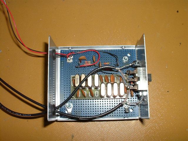
The next part of the project was to decide what the finished product was going to look like. It was going to sit on top of my 509, and there wasn't much to the actual circuit so it could be pretty small. I put it in a metal project box that I got from Radio Shack. They don't have them anymore, but my next choice would be to get something from TenTec to match my rig. I used 0.1" grid perfboard and did most of the soldering under the board. The layout in the photo worked out pretty well, and the only change I might suggest is to rotate the amplifier circuit so it has its Input near the slide switch, and the Output near the far end of the crystal filter. This is more an aesthetic change than a functional one; it just makes for a cleaner signal flow. Notice that the coax shields get tied to ground lugs mounted behind the slide switch ears, and a ground lead runs down to the amplifier circuit. The amplifier circuit ground is connected to the crystal filter Input ground. You can use either end of the #517 filter for Input. My layout uses the "back" end as the Input so that the Output of the filter is close to the switch. Power for the amplifier stage in the external filter comes from either one of the two 12v auxiliary phono connectors on the back apron of the rig.
N4EY's article describes the interface with an Omni 540, but it wasn't hard to figure out where the insertion point should be in an Argonaut. I removed the bottom cover and went straight to the IF Board. Locate Q1 (it's in the "southwest" corner of the IF Board if you think of the front panel as being "north"). Locate C1, and cut the lead that goes to the "IN" pin on the IF Board. This is the second pin from the corner (see photo). The first pin is, conveniently, a ground. When you cut the lead to C1, leave enough on the board and on C1 to solder to. Solder the center conductor of one of the coax cables to the cut lead sticking up out of the board, and solder the ground braid to the ground lug. (I added a ground lug under the IF Board mounting screw and soldered it to pin 1 of the board. If you solder the coax shields to the ground lug, you'll be less likely to damage the IF board.) This cable is the Input to the external filter, and it goes to the Wide side of the slide switch. Solder the center conductor of the other coax to the flying lead of C1, and solder the ground braid to the same solder lug as the other braid. This is the Output of the external filter, and it goes to the center terminal of the slide switch (see drawing). I routed the two coax cables through the 1/4" SSB connector on the back panel.


Before replacing the back cover, I wanted to make sure this was going to work. I put the external filter in the Wide position, hooked up 12v to the Argonaut, and stuck a piece of solder into the antenna connector. When I turned it on, there was the expected white noise. I tuned around and found a CW signal I could copy. Then the moment of truth... I slid the switch to the Narrow position, and there it was: a nice clean CW signal with most of the noise filtered out. It worked. Now I replaced the bottom cover, and put the other part of the project box on the external filter. At first I tuned around to find signals, and then switching in the crystal filter. Everything sounded good, but I couldn't find two signals close enough together to give it a real test. Finally, I just tuned to the side of a strong signal in the Wide mode, and then switched to the Narrow mode. The signal was gone. I made a few contacts just to make sure nothing had happened to the transmit signal (all was OK), and declared the project a success.
This is a pretty easy project. The hardest part was the mechanical design of the filter box. There are no permanent mods to the Argonaut. If you ever want to un-modify the rig, just unsolder the two cables from the IF Board, and reconnect the cut lead on C1.
Many thanks to Steve, N4EY, for being the pioneer for this project and for sharing it with the rest of us. It's worth pausing to consider that his article appeared in QST 25 years ago, and we are still benefiting from it today. 'way to go, Steve.
If you have any questions about my write-up of this project, please send me an email. And by all means send an email to Steve (hiscallsign@arrl.net) to thank him for his efforts.
73,
ed - k9ew